01Single-axis embedded control prototype
Arduino Solar Tracker
Renewable EnergyMay 2025
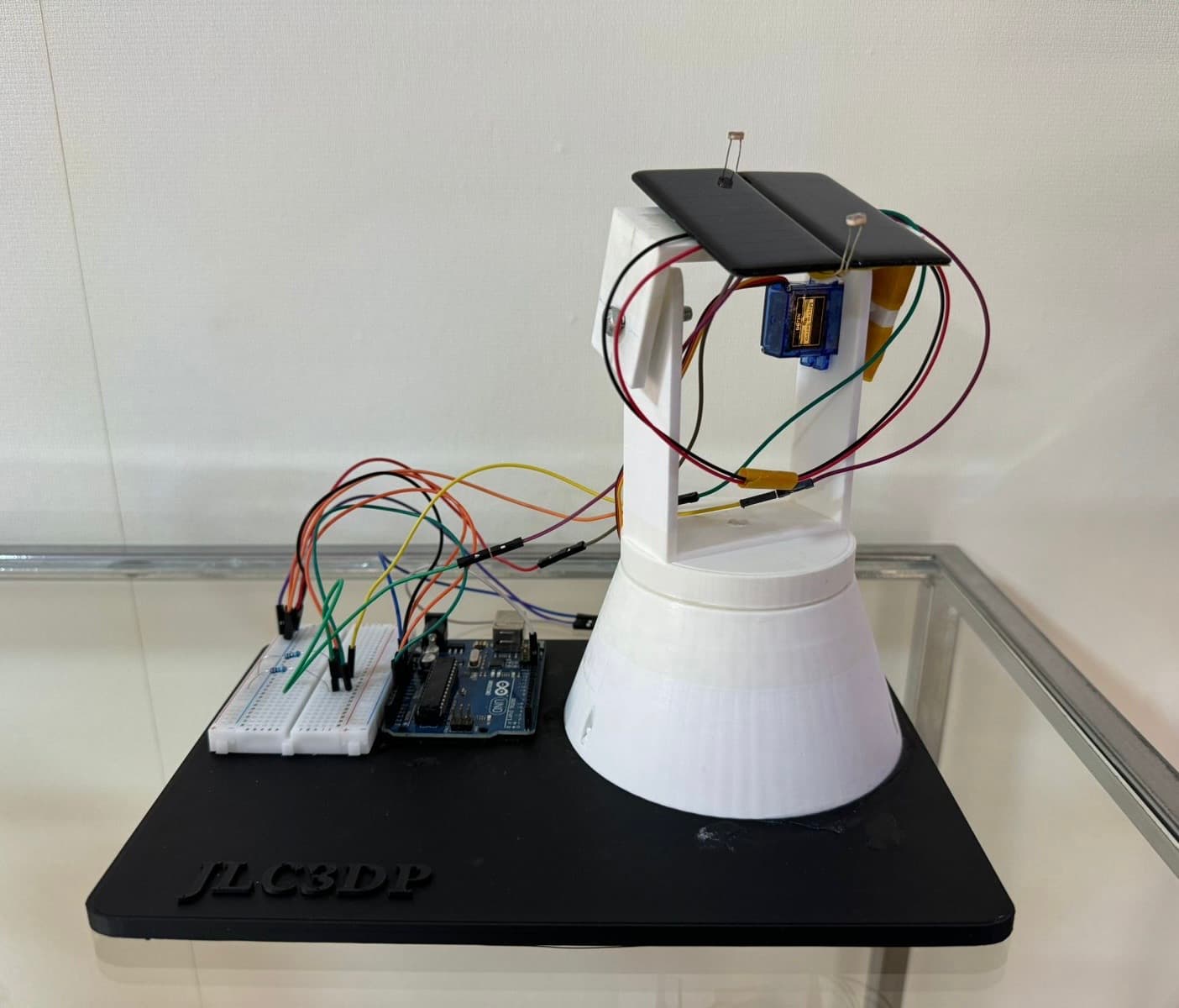
Built for EE 312, this three-person team project uses differential light sensing and incremental servo control to turn a small panel toward the brighter side. The result is a complete sensing-to-actuation prototype developed through simulation, fabrication, and physical testing.
02Context
Project Overview
The Solar Tracker is a light-following, single-axis prototype developed for EE 312, Electronics I. The team designed the circuit and control behavior in Tinkercad, assembled the electronics, fabricated a supporting structure, and transferred the validated program to the physical build.
Two light-dependent resistors provide directional input. An Arduino UNO compares their readings and commands an SG90 servo in small increments, while a barrier between the sensors creates useful contrast.
The completed system responded to directional light indoors and outdoors, validating the integration of sensing, control, actuation, and the supporting mechanism.
03Definition
Engineering Problem & Objectives
A fixed orientation cannot respond when the strongest light direction changes. The engineering problem was narrowed to automatic alignment on one axis using accessible components and a method that could be simulated before construction.
The objective was an educational prototype, not a production installation. That boundary kept the work focused on sensing, actuation, alignment, and validation.
- 01Detect the brighter direction with two analog light sensors.
- 02Convert sensor resistance changes into readings the Arduino can compare.
- 03Move a panel incrementally toward the stronger light source.
- 04Avoid unnecessary servo movement when the readings are close.
- 05Validate the circuit and logic virtually before physical assembly.
- 06Integrate the electrical, software, and mechanical subsystems in one prototype.
04Operation
How the System Works
The tracker repeats one sensing-and-control loop, from creating directional contrast at the sensors to updating the panel orientation.
- 01Light direction
- 02LDR sensing
- 03Analog readings
- 04Arduino comparison
- 05Control decision
- 06Servo movement
- 07Updated orientation
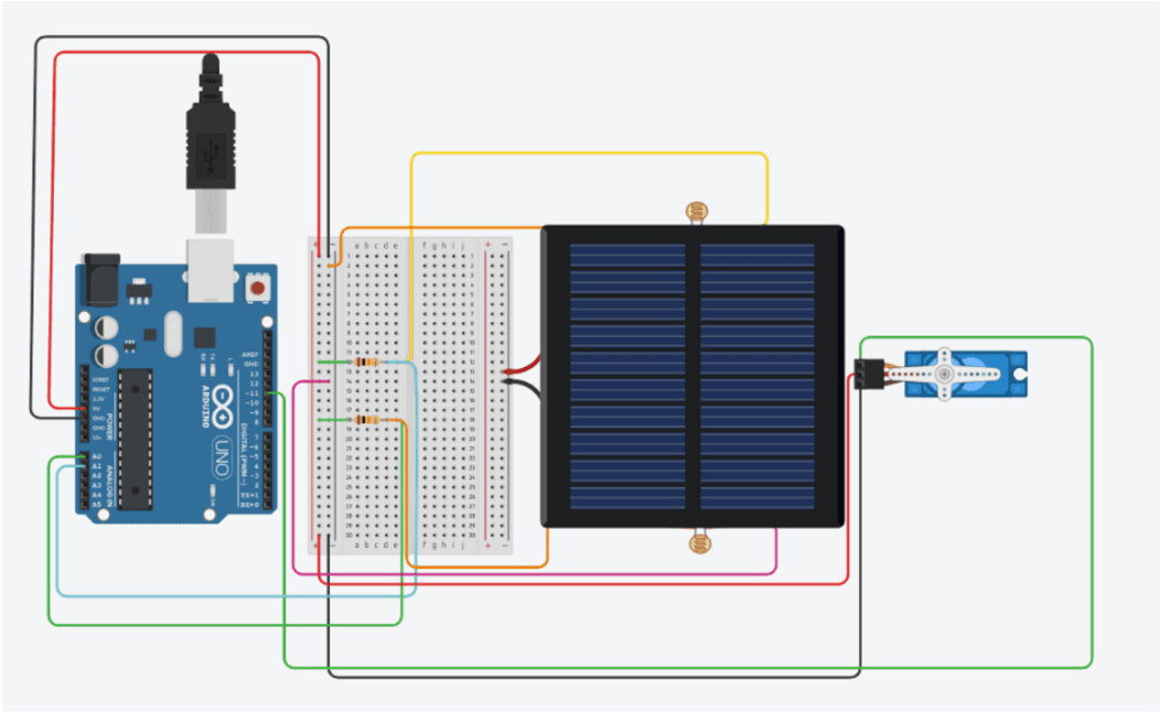
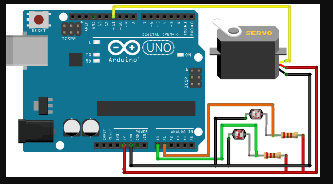
The two LDRs sit on opposite sides of a vertical barrier. Uneven illumination changes their relative resistance, while paired voltage dividers translate those changes into analog voltages.
The Arduino evaluates the inputs and either holds position or changes the servo command. The servo turns toward the stronger reading, then the next loop evaluates the new orientation.
05Hardware
System Architecture & Components
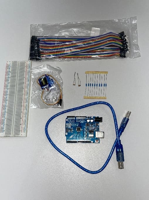
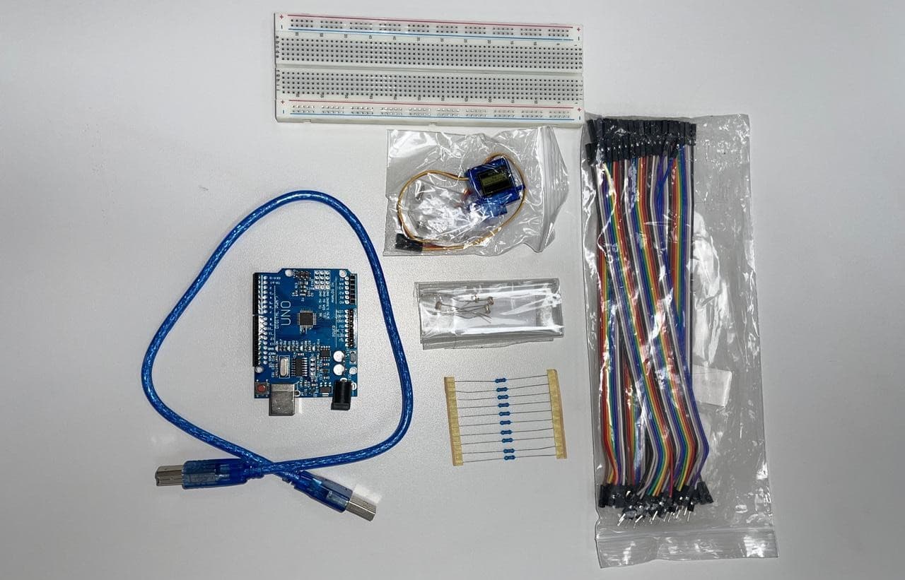
The physical architecture combines a small set of readily available parts. Each item below is described by its role in the implemented system rather than by a generic component definition.
Arduino UNO
Samples both analog inputs, applies the comparison logic, and sends position commands to the servo.
Two LDR sensors
Provide the paired light readings used to determine which side is brighter.
10 kΩ resistors
Complete the two voltage-divider circuits that convert LDR resistance changes into measurable voltages.
SG90 servo
Turns the mounted panel in response to incremental position updates from the Arduino.
Breadboard and wiring
Connect the sensing circuits, controller, power, and actuator during prototype assembly.
Vertical sensor barrier
Creates directional contrast by shading one LDR more than the other when light arrives from the side.
3D-printed structure
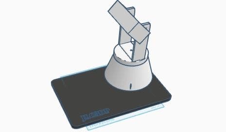
Holds the servo, panel, and sensors in a repeatable mechanical arrangement.
| Component | Role in the prototype |
|---|---|
| Arduino UNO | Samples both analog inputs, applies the comparison logic, and sends position commands to the servo. |
| Two LDR sensors | Provide the paired light readings used to determine which side is brighter. |
| 10 kΩ resistors | Complete the two voltage-divider circuits that convert LDR resistance changes into measurable voltages. |
| SG90 servo | Turns the mounted panel in response to incremental position updates from the Arduino. |
| Breadboard and wiring | Connect the sensing circuits, controller, power, and actuator during prototype assembly. |
| Vertical sensor barrier | Creates directional contrast by shading one LDR more than the other when light arrives from the side. |
| 3D-printed structure | Holds the servo, panel, and sensors in a repeatable mechanical arrangement. |
06Reasoning
Key Engineering Decisions
Six decisions kept the prototype understandable, buildable, and appropriate for a first electronics course.
01
Two sensors instead of four
A paired LDR arrangement was sufficient for the selected axis, reducing input count, wiring, and control complexity.
02
Single-axis tracking
One rotational degree of freedom matched the educational objective and avoided the added mechanics and software required by dual-axis motion.
03
A vertical barrier
Separating the sensors with a physical shade made side-to-side illumination differences easier to distinguish.
04
A threshold of 10
Testing selected a 10-unit deadband so small variations would not trigger continuous corrective motion.
05
Small angular corrections
The program changes the servo setpoint by approximately one degree per correction, producing gradual rather than abrupt movement.
06
Simulation before construction
Tinkercad provided a low-risk way to check the circuit, comparison logic, and bidirectional servo response before physical integration.
07Software
Control Logic
The verified program starts at 90 degrees, reads A0 and A1, compares the values, updates the position when required, writes to the servo on pin 11, and waits 80 milliseconds before repeating.
- 01Read the two LDR values from analog inputs A0 and A1.
- 02Calculate the absolute difference between the readings.
- 03Compare that difference with the configured deadband.
- 04Leave the position unchanged while the difference remains within the deadband.
- 05Decrement the servo setpoint when LDR1 is stronger.
- 06Increment the setpoint when LDR2 is stronger.
- 07Write the updated position, pause briefly, and repeat.
Arduino C++
int ldr1 = analogRead(LDR1);
int ldr2 = analogRead(LDR2);

int value1 = abs(ldr1 - ldr2);
int value2 = abs(ldr2 - ldr1);

if ((value1 <= error) || (value2 <= error)) {
    // Keep the current position.
} else {
    if (ldr1 > ldr2) {
        Spoint = --Spoint;
    }
    if (ldr1 < ldr2) {
        Spoint = ++Spoint;
    }
}

servo.write(Spoint);08Virtual validation
Simulation & Validation
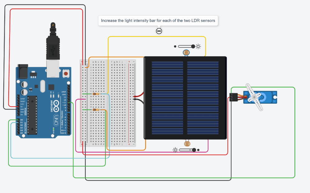
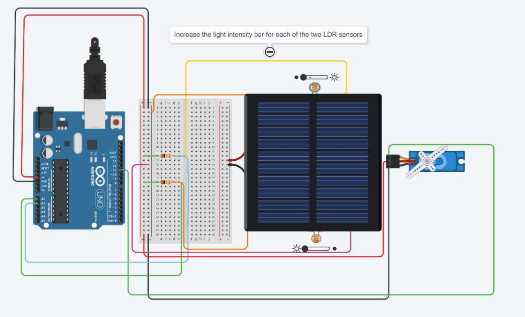
Tinkercad Circuits validated the electronic configuration and software behavior before assembly. Varying each photoresistor independently confirmed the comparison, movement toward either side, and stationary behavior when the readings were close.
The same control program was later uploaded to the prototype. Simulation reduced implementation risk by exposing wiring and logic issues early, but it was not treated as proof of real-world performance.
What the simulation could not validate
Tinkercad simplified the LDR response and displayed servo rotation without reproducing the complete three-dimensional mechanism. It also did not represent physical load, alignment error, reflections, voltage variation, or long-term outdoor conditions.
09Construction
Physical Implementation
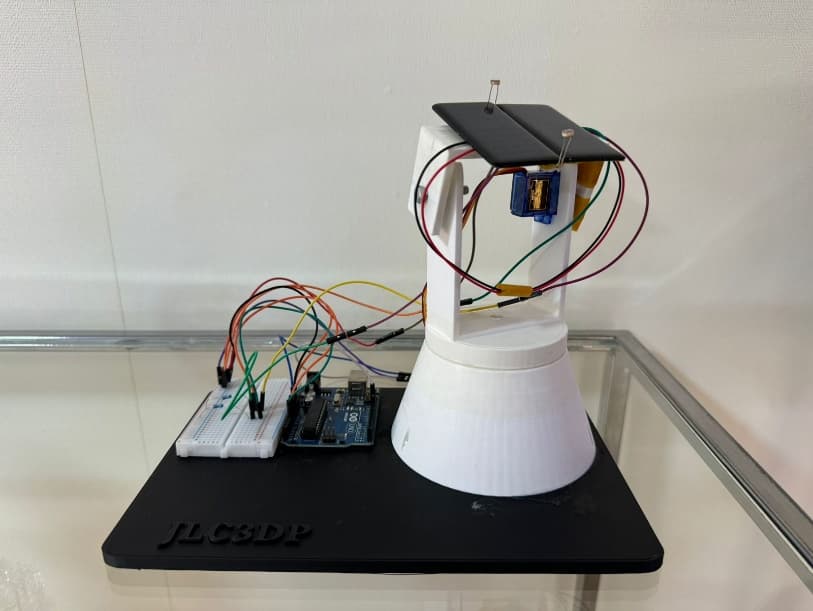
Physical construction began with two LDR voltage dividers connected to the Arduino. The SG90 provided the mechanical output, while jumper wiring joined the sensing, control, power, and ground paths.
The 3D-printed structure located the servo, supported the panel, and held the sensors around the barrier. Sensor spacing and barrier alignment affected the readings before the software made a decision.
After assembly, the team uploaded the simulated program and checked the response under directional light. The physical prototype joined the electrical, software, and mechanical work into one system.
10Evidence
Testing & Results
Directional light changed which sensor received the stronger input. The servo moved toward either side, stayed still when readings were close, and reversed when the brighter direction changed.
Physical behavior closely matched the simulation, and the barrier improved distinction between the readings. These observations support the light-following function but remain qualitative.
LDR1 received stronger light
The servo moved incrementally toward that side.
LDR2 received stronger light
The servo moved in the opposite direction.
Difference stayed within the deadband
The commanded position remained unchanged.
Stronger light direction changed
The prototype reversed its correction.
Virtual and physical implementations
The observed control behavior was closely aligned.
Barrier aligned between the sensors
The two readings became easier to distinguish.
| Test condition | Observed behavior |
|---|---|
| LDR1 received stronger light | The servo moved incrementally toward that side. |
| LDR2 received stronger light | The servo moved in the opposite direction. |
| Difference stayed within the deadband | The commanded position remained unchanged. |
| Stronger light direction changed | The prototype reversed its correction. |
| Virtual and physical implementations | The observed control behavior was closely aligned. |
| Barrier aligned between the sensors | The two readings became easier to distinguish. |
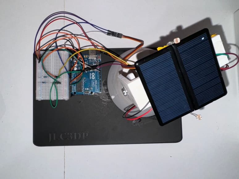
The prototype demonstrated directional light tracking. It did not measure photovoltaic power output, energy gain, or efficiency improvement over a fixed panel.
11Reflection
Challenges, Limitations & Takeaways
The prototype is most credible when its demonstrated behavior is separated from the conditions it did not measure or endure.
Challenges encountered
- Ambient light, reflections, and shadows could change the relative sensor readings.
- Sensor spacing and barrier alignment affected the directional contrast available to the controller.
- Breadboard wiring and the printed mechanism had to remain secure while the servo moved.
- Virtual behavior had to be translated into a physical system with real alignment and load effects.
Prototype limitations
- Movement was limited to one axis and used light intensity rather than calculated solar position.
- The mechanism remained a prototype-scale indoor construction rather than a weatherproof installation.
- Photovoltaic voltage, current, power, energy, and comparison with a fixed panel were not measured.
- Long-term reliability and outdoor environmental exposure were not tested.
Engineering takeaways
- Simulation reduced implementation risk without replacing physical validation.
- A deadband can stabilize a simple sensor-driven controller.
- Mechanical alignment directly influences the quality of sensor-based decisions.
- A small architecture can satisfy a carefully bounded prototype objective.
- Embedded systems depend on electrical, software, and mechanical integration.
12Next steps
Future Direction & Resources
Future work would strengthen the prototype through photovoltaic measurement, comparative testing, improved positioning, data logging, and outdoor-ready construction.
Future direction
- Add a second axis for vertical adjustment.
- Integrate a real photovoltaic cell and a suitable electrical load.
- Measure voltage, current, power, and accumulated energy.
- Compare collected energy against a fixed reference panel.
- Combine light sensing with real-time-clock-assisted positioning.
- Log operating data and present system status on a display.
- Design a weather-resistant enclosure and outdoor mounting system.
Curated gallery